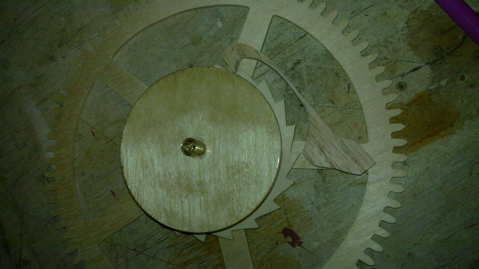
Previously, I haven't made key-wound mechanisms, so Clock 4 is to be driven by a roughly 1" barrel wound with a key. The drive wheel rides loosely on the barrel arbor, which is (at least for now) friction-locked onto the barrel.
The barrel arbor has a 1/8" plain pivot that fits a hole in the back plate. To engage the key, there is a cross drilling for a steel pin. The drive wheel is supported in a cock screwed onto the back plate.
The drive wheel meshes with a pinion that directly drives the escape wheel.
The pinion rides on a small arbor that itself screws into the back plate.
I will cut away some of the cock to allow clearance for the escape wheel, which also will carry the minute hand (directly). I also plan to try Aaron Dodd Crane's daisy wheel motion work to drive the hour hand coaxially.
Yesterday was busy! I got clock 3 to the point where the escapement runs, but the clock doesn't yet sustain more than two ticks at a time... More debugging to come.
I started by putting a brass steady pin in the shelf to engage the center cock.
Here's the cock installed.
The clock is to be mounted on the wall, and I just learned about French cleats. That seemed a pretty cool way to mount the clock! I took a piece of pine and planed a 45 degree bevel, and mounted it level on the wall.
The matching cleats for the clock were similarly planed from oak...
... drilled ...
and mounted on the clock.
The drive wheel rides on two-piece arbor I built yesterday, but I had to wait for the polyurethane to dry on the barrel. The arbor was pushed into the barrel in the vice.
After that, I cut a click spring from a thin piece of oak and superglued it into place.
The center arbor was next. Here was the planned construction.
One notable features is that even though the hour finger is to run with the center wheel, it is not directly connected. The center wheel is held on with tight friction, but can still slip on the arbor. The hour finger cannot slip. This allows the hands to be set by turning minute hand -- rigidly attached to the center arbor, which turns the hour finger, and thus sets the hours synchronously while the train slips.
After cutting, I tried the fit in the frame. This required broaching the cock pivot hole to fit, and quite a bit of sanding on the foot of the cock to get the holes into alignment. Evidently my original drilling wasn't square... But in the end, I got it to fit and run smoothly.
The hour finger is fit onto a squared portion of the center arbor, which I held on with a washer on the other side. The washer was attached with Loctite 603. I'll worry about the hour rack later.
The other arbors are screwed into the back plate. I found that oak can be tapped for 6-32 threads if a 7/64" hole is drilled first.
The brass arbors are turned to 1/8" and threaded with 6-32 threads to a length of 3/8".
The train runs more smoothly than and I've made before, so that's a nice payoff for the large investment of time I made on getting the wheels sanded perfectly.
Now for the detent. The locking pallet was turned, pressed into place, and then the locking face was filed. All of this was done on the lathe to ensure a good grip.
I decided to make the foot spring from the detent itself by thinning the wood. The foot is then screwed onto the detent cock. Here are two views of the detent in place.
The detent also needs an unlocking spring. This was cut from a segment of a spring taken from a broken toy car.
The hole for the spring was punched...
... and a mounting pin turned to fit.
The pin was then staked in place.
Here's the detent installed. It seems to require close installation tolerance to run.
Now, as for running, the escapement will unlock properly, though it takes a bit of tuning. It is also quite loud... far louder than even I would like for a long-running clock. Even though the clock is quite handsome, if it works, it will probably stay out of living spaces... Sadly, that's less motivation to finish the motion work...
It seems that the balance looses energy too quickly to actually work. There are apparently a few issues:
Since the foot spring on the detent is stiff, the unlocking takes a good deal more energy than expected. Most books I've read on the subject seem to largely neglect the foot spring energy altogether. The fact that I can't points to a design problem. The balance could be too light -- therefore the unlocking represents a larger fraction of the balance's kinetic energy -- or the spring could be too stiff.
Even without the influence of the escapement, the balance slows to a stop quickly. This also points to loosing too much energy. However, making a heavier balance does not fix this problem, and probably makes it worse.
I could get the clock to run consistently by manually applying force to the fourth
wheel, but not to the center or drive wheels. I found that taping small
weights (in about 1/12 ounce increments, from pinewood derby cars) to the wheel helped getting the
balance to have enough energy to unlock. Even then, the oscillations quickly died out even with a frightfully large drive weight (7.6 lb) on the drive wheel. I am definitely unhappy with that much weight, given the delicacy of the movement.
The frame for clock 3 is intended to be unobtrusive. It supports the arbors on which most of the wheels spin, except for the center wheel which is supported between two pivots. I depthed the wheels with the depthing tool and marked their centers directly on the piece of oak that is to become the frame.
I decided to recess the frame like a watch, so that the different wheels are set into the frame to result in a thinner movement. This ought to keep the center of gravity closer to the wall. I cut the recesses freehand using a router before cutting the frame. Although this worked, it wasn't as precise as if I milled it.
After cutting the recesses, I cut the frame out.
Once cut, I tried the wheels in (no arbors) to fit. Here are two views.
The detent and the center wheel are supported on two separated cocks attached onto a shelf that mates with the back frame.
The detent cock is set on a threaded rod with a knurled knob that should allow some measure of adjustment once it's installed.
The shelf is supported both by the back frame and two shelf brackets.
Here is the shelf and the wheels, testing for clearance.
The chapter ring is for the minutes only, while the hours are read from a flag attached to the center cock. Here they are both planned out.
Both are marked by holes: small holes for the minutes, larger five minute holes.
The hours are marked in binary.
Here are the frame and non-moving parts of the clock being polyurethaned...
The center cock has a steady pin to aid in proper alignment.
The driver arbor consists of two pieces: an inner rod and an outer sleeve with a hole cross-drilled to engage the winding key.
The other arbors are threaded rods, backed with washers to give wheels clearance from the frame.
Picture says most of it.. I designed a new depthing tool in OpenSCAD that should be a bit more stable than the previous one. It's also intended that the arbors are fixed and the wheels spin around them. The design consists of two parallel bars that hold three I-shaped blocks. The outer two I-shaped blocks are attached to the bars, while the middle one can slide. The left two blocks have arbors through them. The sliding block is locked by tightening a knurled nut holding everything together.
Since I had sooooo much trouble driving the turns I made, I had to think of other options. I realized that it might work to take the idea of a super-glue arbor for the lathe, and anchor the pulley to part with super glue.
Anyhow, I turned a very small pulley from 1/4" brass rod.
Here it is attached to the part with a tiny drop of super glue, viewed under the microscope and mounted in the turns.
It's still quite difficult to operate, but seems much less troublesome.
I added an electric motor drive that seems to make it easier to use. I guess it's now a lathe...
I made considerable progress on my timer over the past two weekends. I started with a pile of parts (after sanding)...
... and ended up with a nearly complete, partially functional timepiece!
Here is how it happened...
Since the design phase, I had left the spacing between the two plates as a yet-to-be determined variable. The key distance was the winding barrel, which had to rotate freely around the main wheel's arbor and engage with the ratchet and click assembly. I wasn't quite sure how much room I'd need, so I built the winding barrel first.
The winding barrel is hollow, and has two transverse pins to anchor the winding ribbon. First, I turned the outside of the winding barrel from 1/4" brass rod. Notice the thicker end (left) to receive the ratchet wheel.
I filed flats on the narrower portions...
And drilled holes to receive the pins in the flats.
I turned the pins from 1/8" brass rod, tapered to fit into the holes.
I pressed the pins into place with the vice.
This wasn't secure enough to keep the pins in place while center drilling, so I also soldered them.
I center drilled the assembled winding barrel in the lathe.
After it was drilled, it was fit friction-tight into the ratchet wheel.
Now that I knew the length of the winding barrel, I could estimate the distance between plates. Here are the two standoffs that hold the plates in place.
I also fabricated four pivots and two hollow bushings for the three arbors.
Here are the main wheel pivots drilled and fit into the frame.
Once that was all in place, I turned the main wheel arbor so that the winding barrel fit around it. I turned this out of a single piece of 1/4" brass rod, which took a while.
Then, I pressed the assembly together -- the winding barrel is permanently captive on the arbor.
With the main wheel assembled, I could align the main wheel pivot and bushing by aligning the two plates. This ensured that the arbor was installed perpendicular to the plates; if I had assembled the plates first, there was the risk that the pivot and bushing centers might be slightly out of alignment.
Next, I started to assemble the winding mechanism. Here is the click in place; I used a short nail with a broad head to attach the click so that it can move freely.
For the spring, I used the drive spring from a broken toy car. (There are lots of toy cars around my house since Theodore loves cars! Whenever a car gets destroyed, I scavenge for useful parts, springs in particular.) The spring was easy to cut with diagonal cutters, and easy to bend to shape with tweezers.
Here is the spring installed with two small finishing nails. I put the nails in first...
... and then trimmed off their points flush with the back of the wheel.
In order to drill the other wheels, I realized that I was struggling to get perpendicular holes since I don't have a drill press. So, I made a clamp assembly for my lathe's flat faceplate. I started with a sheet of steel and drilled four mounting holes. I think that the steel was probably hardened, and I was unable to anneal it with my small propane torch. Anyway, I broke two drill bits. One was a carbide-tipped bit for drilling glass, which cracked -- thankfully after finishing the holes!
Then, came the job of cutting the clamps out. Again, much tool stress later (wore out the teeth on my hacksaw and two jeweler's saw blades), I had my clamps. I filed them neatly, so they wouldn't mark anything.
Here they are, holding the second wheel securely in place. I also made use of a wobble stick to get the center just right.
And with that, turned a simple arbor and fitted the wheel and pinion into the frame.
Now, on to the escape wheel. Again, it was important to get the size of the escape wheel before making its arbor. The escape wheel consists of two three-toothed wheels, held part by three brass pins. Here are the pins, turned from 1/8" brass rod.
The pins are pressed into holes on each of the wheels, forming the escape wheel.
Now, with the escape wheel sized, I was able to figure the length of the arbor. I learned my lesson with the main wheel: turning down a 1/4" brass rod to 1/8" over nearly its entire length so that you have a hub takes long time. To economize on time a bit, I turned the arbor from 1/8" rod brass, and made a separate hub from 1/4" brass rod.
These two items were soldered together, thereby avoiding waste of time and materials.
The escape pinion was pressed on, using my now-standard technique of pressing on the lathe.
As usually happens to me, the depthing for this wheel wasn't perfect. So I opened up the bushing and pivot holes a bit and shimmed them to fit.
Here, the escapement wheel is pressed into place on its arbor. This means that the escape wheel and its pinion are permanently attached to the outer plate.
Trial assembly; most everything seems to fit. The wheels turn (mostly) smoothly, with the escape pinion occasionally binding. That'll be a problem for later, but it will need to be managed... Anyhow, this was the end of the first weekend, probably about 10 hours in total.
The second weekend started with making lots of pins... There are (top to bottom) 2x locking pins, 2x pendulum crutch pins, 2x gravity arm pivots, and a pendulum support.
Here are the locking and crutch pins installed on the gravity arms.
Here are the gravity arm pivots. It turned out that I had made these too short, so I put washers in as a stop-gap measure. Will need to fix later.
The pendulum support rod was set up in the style of what's shown in Gary Mahoney's clock:
I slit my pendulum support rod with a jeweler's saw, filed two flats, and then drilled to receive a screw.
This allows the pendulum to be attached with a flexible hinge of some sort. For the moment, I'm using paper. Maybe I'll use a flat spring.
The whole mechanism is assembled and mounted!
It runs, somewhat intermittently, with 4lb 4oz of weight! It is noisy!
The key issues seem to be that
The escape pinion binds occasionally, stopping the clock
The escape wheel occasionally skips, in which it slips past its locking pin rather than being captured. This is kind of catastrophic since the pendulum receives an out-of-phase impulse; sometimes it can recover, sometimes it can't. I think the cause is the gravity arms slipping along their pivots.
Remaining tasks:
Cap off the ends of the gravity arm pivots. The arms tend to slip around and off the pivots
Fix the gravity arm pivots by either remaking them (preferable) or making custom washers so that they keep the gravity arms the correct distance away from the outer plate.
Fix the depthing of the escape pinion
Fabricate a pendulum bob. The current bob is attached with a rubber band
Replace the pendulum pivot with something a bit stiffer than paper -- the pendulum wobbles axially too much.