Showing posts with label lathe. Show all posts

Sunday, July 5, 2020

Small shepherd's sundial

Some time ago, I made a simple wooden shepherd's sundial.  It's crude and doesn't work well, but I set it on a lanyard and occasionally use it.  When I decided to use it recently, my wife asked for a small one as a necklace.  Commissioned artwork time!

Since I wanted the sundial to be stylish as well as functional, I thought a bit about materials.  I ended up with a simple design that uses 3/8" copper tubing.  It's the same stuff that you can get at the hardware store for various plumbing jobs, but it's small enough for the task.  I traced out the hour lines using a short python script, and printed them out for use as a guide.


The gnomon is held in a steel cylinder with a slight lip to retain it inside the copper tubing, which has a matching (reverse) lip bored in the end.  You slide the cylinder in from the bottom of the sundial.  Boring the copper was a bit of a problem until I got the boring bit set properly.  I also ended up bursting through the side of the first cylinder because I didn't correctly account for the thickness of the tubing. 

I cut the tubing with a jeweler's saw and filed it to final shape for the noon curve.   The cylinder has two drillings: an axial drilling for the hanging loop and a radial drilling for the gnomon.  The hanging loop is just a piece of brass wire bent into a loop at the top.  I thought of soldering it in place, but decided not to.  I hammered the bottom end of the wire into a small rivet, so the loop is free to turn. 

Here is a trial assembly.


I spent considerable time polishing the copper, the pin, and the cylinder.  The machining was not too arduous, though it did take a few tries, but the engraving was much more tricky.

Here's the final product.


I did not use a watchmaker's square graver (too unwieldy on the round surface) nor the more usual round graver (difficult to get it to bite consistently) to do the engraving.  After a bit of trial on a scrap piece of copper tubing, I found that a very small screwdriver that I had previously sharpened to a narrow cutting blade worked much better for engraving.

To keep everything aligned, I taped the printout to the surface of the copper, and cut through the paper.  This got the copper marked in roughly the right places.  Then I removed the paper and finished the engraving under the microscope.  This took about an hour, and was a bit nerve-wracking because every slip-up is visible.  I'm not too proud of how the engraving came out -- many slips, wiggles, and other awful mishaps are visible if you look closely.  However, it doesn't look embarrassingly bad if you don't use a microscope. 

The sundial certainly looks nice enough on its own, but I am not sure how practical the shiny surface will be in use.  It's cloudy now, which might be for the best!
Thursday, May 30, 2019

Astrolabe upgrade

American University's Design and Build Lab got a new laser cutter.  Since the astrolabe I made before was drawn as a set of SVG files, I figured that it might be nice to make another astrolabe on the laser cutter.  Indeed, the result is beautiful!


This astrolabe is cut from 1/4" black acrylic with a 1/8" clear acrylic rete (star chart).  I etched the rete on the back of the clear acrylic, so there is no visible parallax error.  The pointer is 3d printed PLA. The brass hardware was hand turned on my lathe.  All of the hardware is friction fit with no adhesive used.  This astrolabe is for a fixed latitude (39 degrees North), so the center pin is (essentially) permanent.  The movement is smooth, but tight.  This is a nice improvement over my previous astrolabe, in which the hole in the rete has enlarged over time.

Unfortunately, we had trouble aligning the back.  The horizontal alignment is perfect, but it's vertically shifted by about 2 mm.  This means that the elevation scale runs off the top of the astrolabe. None of the back scales are very useful as a result, even though it is still attractive.  I think the cause of the vertical shift was an alignment key (which doubles as the ring attachment point) that we added to the front layer, but not the back layer.  We attempted to compensate for this difference, but evidently failed.  However, the compass scale on the front can still be used for elevation sighting, although this requires subtracting 90 degrees from the reading to obtain elevation.

Monday, December 31, 2018

Clock 4 detent issues

I installed a new(er) 1/3 hp 1725 rpm motor on my lathe since the bearings on the old one were dead.  It runs much better than before!

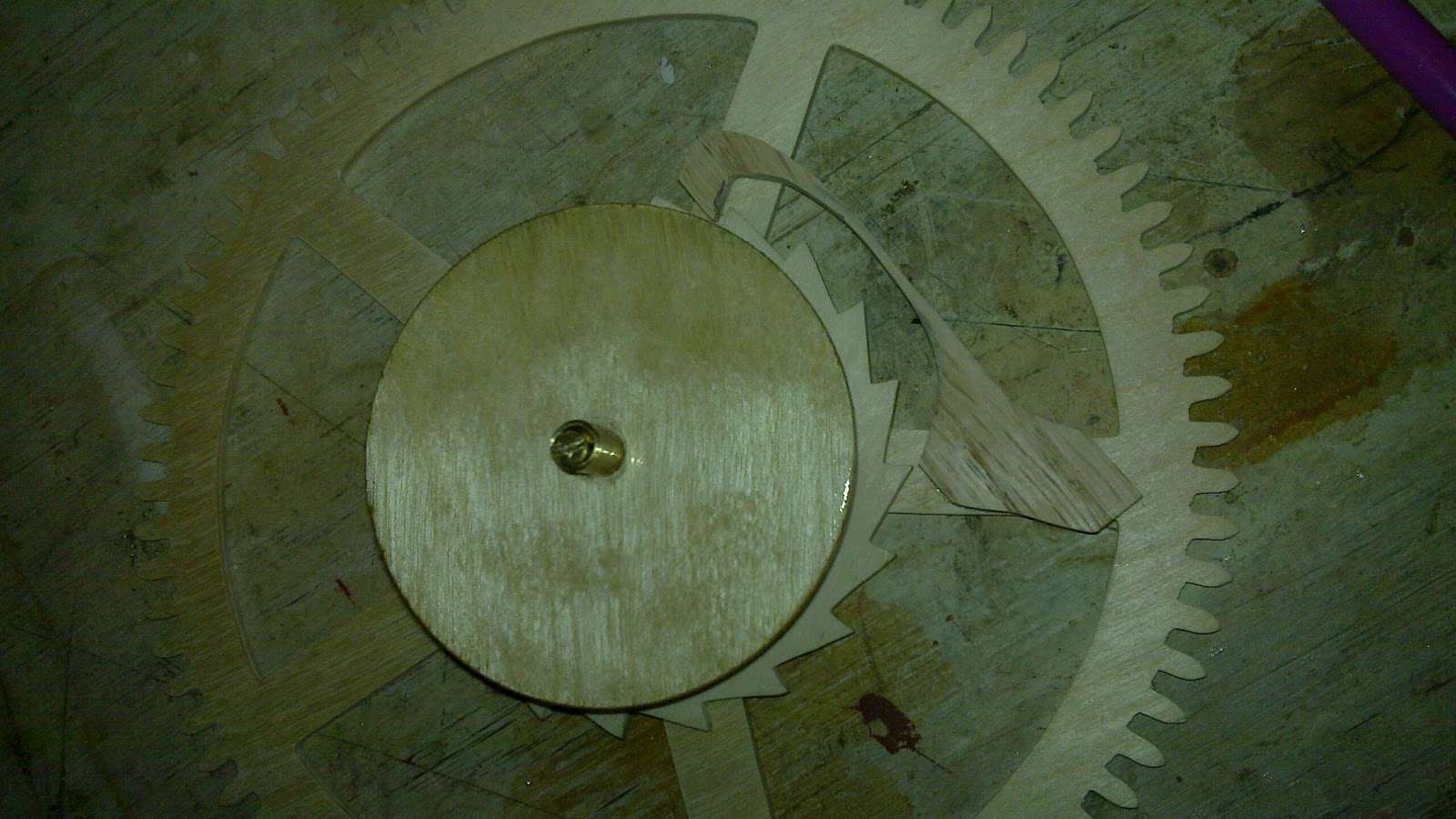
The detent mechanism for Clock 4 uses a gate invented by Philip Woodward (I think).  The detent sits on a pivot near the pin escape wheel.

The detent is fairly long, but just press fit into the frame.

The detent is cut from a small piece of white oak.

Here is the detent after shaping.

There are many issues with the detent, and it doesn't run at the moment:
  • The gate is very thin.  I broke two detents already
  • Woodward didn't seem to bank his detent, but it looks like I need to since wood has more flexibility than metal
  • The catch for holding the pin is very touchy as to how deep it is.  Woodward suggests that it might work as just a small depression, but this caused the pins to jump out.  Too deep, and they can't clear when the escape wheel recoiled... in which case the pins stick.
  • The pins of the escape wheel are too inaccurate in their placement
  • The pins of the escape wheel are too inaccurate in their vertical alignment
  • The pins of the escape wheel are not all the same diameter (because some of them split in the process of being installed).
  • The relative positioning of the catch and the gate slot is quite delicate, and there isn't much clearance.
  • The counterweight portion of the detent governs how much weight is needed to run the escapement.  This needs to be very light.
A few times, I could feel the escapement "almost working" under my hand, but it wasn't consistent enough to run under a weight.

Sunday, December 16, 2018

Clock 4 drive assembly

Previously, I haven't made key-wound mechanisms, so Clock 4 is to be driven by a roughly 1" barrel wound with a key.  The drive wheel rides loosely on the barrel arbor, which is (at least for now) friction-locked onto the barrel. 


The barrel arbor has a 1/8" plain pivot that fits a hole in the back plate.  To engage the key, there is a cross drilling for a steel pin.  The drive wheel is supported in a cock screwed onto the back plate.


The drive wheel meshes with a pinion that directly drives the escape wheel. 


The pinion rides on a small arbor that itself screws into the back plate.


I will cut away some of the cock to allow clearance for the escape wheel, which also will carry the minute hand (directly).  I also plan to try Aaron Dodd Crane's daisy wheel motion work to drive the hour hand coaxially.

Saturday, January 27, 2018

Saxaphone ligature screw


Edwin's saxaphone ligature takes two 6-32 screws.  One of them broke, so I made a replacement.  I started with 1/2" diameter steel rod.  I think it was zinc plated, but that wasn't too critical; whatever plating was originally there was removed.

I started by turning the portion to be threaded to 1/8".  Since the length wasn't too critical, I just used the good screw to figure the length.


I threaded the end by hand.  (I could have used a geometric die, but the setup would have been longer...)


Once threaded, I turned the shoulder that separates the threaded portion from the handle.


The shoulder actually tapers a bit, which I did with the graver.


The handle is a rounded ball, which I shaped with the graver after using a parting tool to remove most of the waste.

Here is the part next to the broken screw after parting.


I removed the leftover spigot by reversing the screw in the lathe -- good thing I have an 1/8" collet.


Now the handle is ready for final shaping.


Since I had to remove lots of material, I figured I could either spend time with a file or the bench grinder.  The bench grinder seemed like the better option (it may not have been any faster, actually).  I gripped the part in a pin vice so that I was securely in hand.


I ground both flats with numerous breaks to dunk in cool water...


After polishing, hardening, tempering, and final polishing, here is the final product in place.


The handle is a little wider than the original, but it does the job.

Thursday, January 4, 2018

Extreme IC repair

For Christmas, our family of hams got Cricket 80A transceiver kits.  They are not terribly hard to assemble and are good soldering practice. 

One problem we had with two of them was that the local oscillators did not start up.  It turned out that the 2N7000 MOSFETs are susceptible to electrostatic discharge (ESD) damage.  For whatever reason, the Q1 local oscillator transistor seems more vulnerable to this.

But in one of the kits, there was a problem with the audio amplifier IC, an NJM-2113D.  In the process of soldering and apparently removing, three pins broke off.  These are not exactly standard, at least they're not in my junk box. So although I put in an order for a replacement, Donna pointed out that I could probably fix it anyway.

The issue is that pin 1 (GND) broke off at the case, so I set about using a four fluted 1/8" endmill to cut the case to expose more of the pin.  I gripped the endmill in a collet in the headstock of my lathe.


My biggest concern was part-holding.  Fortunately, I was able to grip the IC in a toolpost, which also didn't break it.


After a few passes, I successfully exposed what seemed like enough of the pin to take solder.

I started by soldering the intact pins to the board and then the third pin, which was broken off, but not all the way at the case.  For this, I ran a piece of tinned copper wire through the hole, soldered it to the board, and then to the IC.


Then I ran another piece of tinned copper wire through the hole for pin 1 until it stopped on the exposed part of the IC, and soldered it to the board.


Finally, I soldered the new pin 1 to the IC.  I used a bit too much solder, but it's a good connection.


And, it works!  Here is the happy owner of the completed radio.


Sunday, March 19, 2017

Clock 3 first tick

Yesterday was busy! I got clock 3 to the point where the escapement runs, but the clock doesn't yet sustain more than two ticks at a time... More debugging to come.

I started by putting a brass steady pin in the shelf to engage the center cock.

Here's the cock installed.

The clock is to be mounted on the wall, and I just learned about French cleats.  That seemed a pretty cool way to mount the clock! I took a piece of pine and planed a 45 degree bevel, and mounted it level on the wall.

The matching cleats for the clock were similarly planed from oak...

... drilled ...

and mounted on the clock.

The drive wheel rides on two-piece arbor I built yesterday, but I had to wait for the polyurethane to dry on the barrel.  The arbor was pushed into the barrel in the vice.

After that, I cut a click spring from a thin piece of oak and superglued it into place.

The center arbor was next.  Here was the planned construction.
One notable features is that even though the hour finger is to run with the center wheel, it is not directly connected.  The center wheel is held on with tight friction, but can still slip on the arbor.  The hour finger cannot slip.  This allows the hands to be set by turning minute hand -- rigidly attached to the center arbor, which turns the hour finger, and thus sets the hours synchronously while the train slips.

After cutting, I tried the fit in the frame.  This required broaching the cock pivot hole to fit, and quite a bit of sanding on the foot of the cock to get the holes into alignment.  Evidently my original drilling wasn't square...  But in the end, I got it to fit and run smoothly.

The hour finger is fit onto a squared portion of the center arbor, which I held on with a washer on the other side.  The washer was attached with Loctite 603.  I'll worry about the hour rack later.

The other arbors are screwed into the back plate.  I found that oak can be tapped for 6-32 threads if a 7/64" hole is drilled first.

The brass arbors are turned to 1/8" and threaded with 6-32 threads to a length of 3/8".

The train runs more smoothly than and I've made before, so that's a nice payoff for the large investment of time I made on getting the wheels sanded perfectly.

Now for the detent.  The locking pallet was turned, pressed into place, and then the locking face was filed.  All of this was done on the lathe to ensure a good grip.

I decided to make the foot spring from the detent itself by thinning the wood.  The foot is then screwed onto the detent cock.  Here are two views of the detent in place.


The detent also needs an unlocking spring.  This was cut from a segment of a spring taken from a broken toy car.

The hole for the spring was punched...

... and a mounting pin turned to fit.

The pin was then staked in place.

Here's the detent installed.  It seems to require close installation tolerance to run.

Now, as for running, the escapement will unlock properly, though it takes a bit of tuning.  It is also quite loud... far louder than even I would like for a long-running clock.  Even though the clock is quite handsome, if it works, it will probably stay out of living spaces...  Sadly, that's less motivation to finish the motion work...

It seems that the balance looses energy too quickly to actually work.  There are apparently a few issues:
  1. Since the foot spring on the detent is stiff, the unlocking takes a good deal more energy than expected.  Most books I've read on the subject seem to largely neglect the foot spring energy altogether.  The fact that I can't points to a design problem.  The balance could be too light -- therefore the unlocking represents a larger fraction of the balance's kinetic energy -- or the spring could be too stiff.
  2. Even without the influence of the escapement, the balance slows to a stop quickly.  This also points to loosing too much energy.  However, making a heavier balance does not fix this problem, and probably makes it worse.
I could get the clock to run consistently by manually applying force to the fourth wheel, but not to the center or drive wheels.  I found that taping small weights (in about 1/12 ounce increments, from pinewood derby cars) to the wheel helped getting the balance to have enough energy to unlock.  Even then, the oscillations quickly died out even with a frightfully large drive weight (7.6 lb) on the drive wheel.  I am definitely unhappy with that much weight, given the delicacy of the movement.