To align holes for each arbor, I made use of the markings for each wheel I had previously made on the middle plate. I carefully drilled through the middle plate with a 1/16" bit. To mark the positions of the anchor hole on the back plate, I aligned the middle and back plates and then drilled through the anchor hole on the middle plate to score the back plate. I did the same (but drilled through the back of the middle plate) to mark the locations for holes of the front plate.
I cut 9 pivot seats (thrust bearings). These bearings are cut from 1/4" brass rod and have a countersunk beveled hole and a small center hole drilled with a 3/32" drill to an additional depth of 1/8". The total length of each pivot is 1/4". (This process takes about 7-10 minutes per bearing.) After drilling and cutting, smoothed the interior surfaces of each pivot with a hand graver and then inspected the surfaces for smoothness at 5x magnification. I didn't polish the bearings, though perhaps this might prove necessary.
To attach a bearing, I first center drilled each location with a 1/16" drill, and then used a 15/64" brad point bit to cut the hole for the bearing. (See below)
I then hammered the bearing (supported by a wooden rod) into its hole.
Once the third, fourth, and escape wheel bearings were set, I tested the fit...
I don't yet have the center or pendulum arbor, so this is as far as the assembly can proceed at the moment. However, there is very little friction. Blowing on the escape wheel is enough to set the mechanism into motion.
Here is how to get a webcam up and running easily on Raspbian... First of all, install fswebcam, which allows you to take single snapshots from a USB-connected (or other) camera. (My webcam is USB-connected.)
$ sudo apt-get install fswebcam
Next, download the Dropbox uploader script and set it up to link up to a folder in your Dropbox account. Then, create a script called snapanddrop.sh somewhere useful. Here's the entire contents (three lines):
This script takes a single snapshot, timestamps it, and then uploads it to your Dropbox area. Incidentally, you can give this Dropbox folder as a link that anyone can use to see its contents. Don't forget to make snapanddrop.sh executable: $ chmod +x snapanddrop.sh
If you want a snapshot any given time, just call snapanddrop.sh from the command line. Finally, I wanted to take a snapshot every ten minutes. This is easily done by adding an entry to the crontab... Simply call
Now that I have all the gears of the train cut, I have an idea of how to arrange them. I could be fancy, but I'm going for simplicity. For the moment, I'm planning to stack the gears vertically as shown in the diagram below.
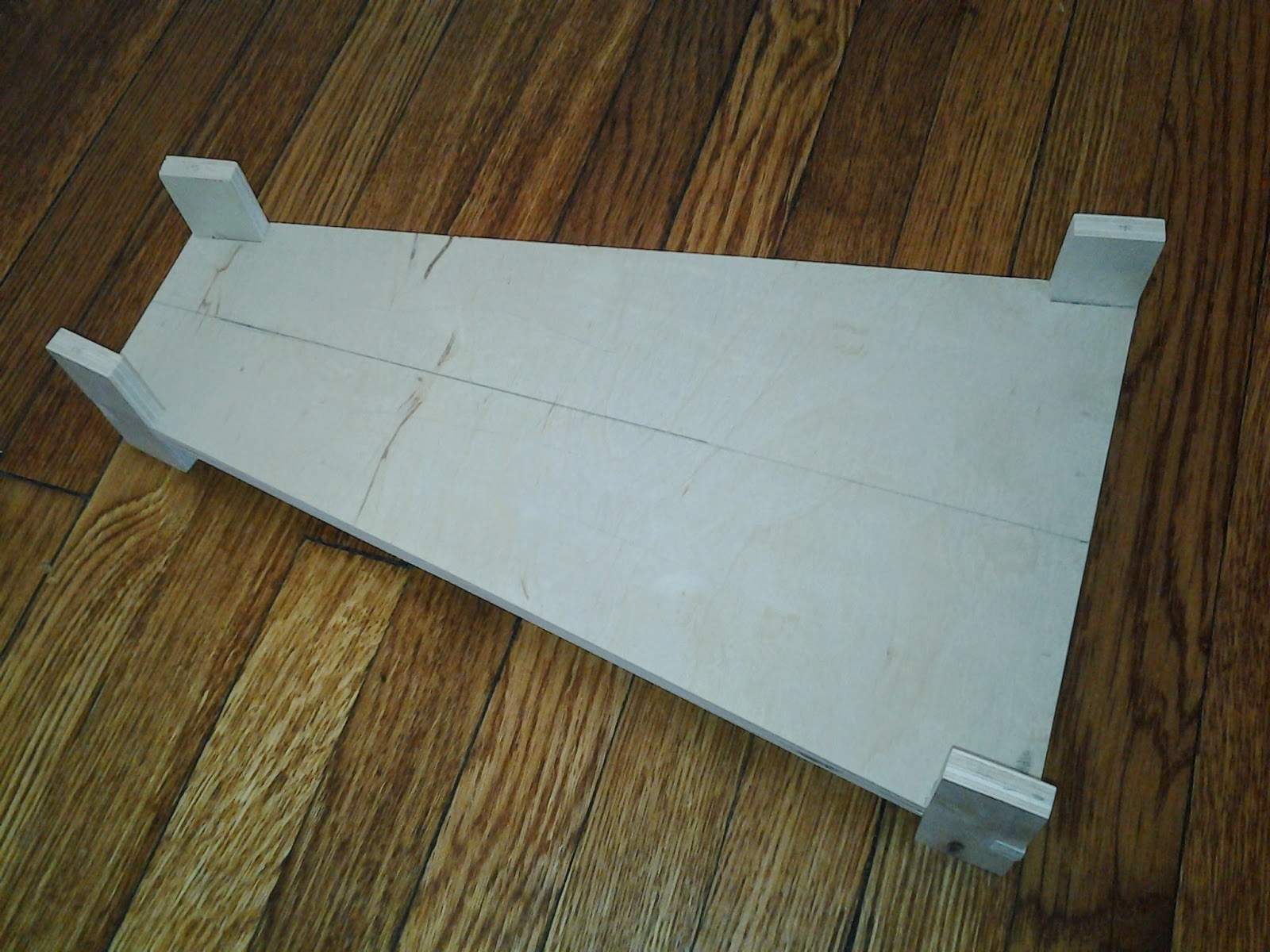
Since the elevation plan I drew before calls for three plates, I cut them...
...freehand using a sabre saw. I used a blade with small symmetric teeth and no orbital to minimize tear out.
The three plates are supported on four corners by notched blocks.
Once cut, I clamped the blocks (and the plates) and sanded them to the same size.
The next step is to cut the notches into the middle plate to match the blocks. This has to be done carefully to ensure proper alignment of the front and middle plates. I did this using the scroll saw to get a rough notch in the middle plate, and then carefully filed until each block fit.
Then using the depthing tool with each pair of gears, I marked the wheel centers.
Here is a plan for a simple clock mechanism with an anchor escapement and co-axial hands.
The drive train has the following teeth counts, which give a ratio of 240:
Escape wheel: 15 teeth, rotates 4 times per minute, 1 second per tooth
Escape pinion: 6 teeth
Fourth wheel: 30 teeth
Fourth pinion: 6 teeth
Third wheel: 36 teeth
Third pinion: 6 teeth
Center wheel: 48 teeth (rotates once per hour)
Thus far, I've cut the center, third, and fourth wheels, along with all of the pinions. The escape wheel remains to be cut, along with the motion work. The motion work includes four gears giving a ratio of 1/12:
Center pinion: 6 teeth (rotates once per hour)
Offset wheel: 18 teeth
Offset pinion: 8 teeth
Hour wheel: 16 (rotates twice per day)
The third, fourth, and escape arbors are as described here. The pendulum arbor is longer. The center and hour arbors are more complex as they need to fit together coaxially as shown below.
The escapement is a deadbeat anchor escapement as shown below.
Because I'm interested in collecting indoor sonar data that has lots of multipath, it is useful to have an omnidirectional antenna either for reception or transmission. Here's a simple design for an antenna that radiates omnidirectionally in the azimuthal plane, but rejects sound from above and below. Roughly, it consists of two round disks with a speaker or microphone placed in the center of one of them. This acts like a cylindrical waveguide.
Before building this, I wrote a simple boundary element method simulator in GNU Octave to test the radiation pattern. This was helpful to choose dimensions for the disks and the spacing between them. The simulator used a dense grid of boundary points (blue below) and propagated to a dense slice of points (green).
After a bit of tweaking, I settled on a separation of 20 cm and a diameter of 60 cm. This yielded a radiation pattern that's roughly flat for equatorial elevations, and drops off sharply beyond that.
Here's a near field plot as well, showing the standing wave structure between the disks.
I constructed the antenna from 1/4" plywood, using 1" dowels as standoffs between the disks. To ensure the standoffs were reasonably precisely made, I faced off their ends in the lathe, and used the lathe to drill pilot holes for mounting screws.
I also cut a tripod mounting bracket using the router.
The speaker is mounted in the center of the top disk.
Here is the finished antenna.
The antenna seems to reject sound from above and below pretty noticeably, but as could be expected from an omni, its overall gain is not very high.
Computer sound cards can record at 44.1 kHz, and the CPU can process this data in real time. With a little thought, this can be pressed into service to make a simple sonar setup. I wrote a small Python program that uses NumPy, GStreamer, and GTK to make a real-time sonar display. With a microphone and reasonable speakers, you can sense moving targets pretty easily. I used cheap, 10 W speakers, and made a low-ultrasound sonar waveform that works well enough.
This picture below shows the setup. The two white speakers emit the waveform. The microphone is a small electret wired microphone and is sitting on the laptop keyboard. The big wooden disk is a target.
The program plays a pre-recorded waveform on the speakers while simultaneously recording audio from the microphone. In essence, the program implements two GStreamer pipelines. A transmit pipeline
which gets restarted every time it finishes, and a receive pipeline
gst-launch pulsesrc ! fakesink
from which the recorded data are snatched from the fakesink using signal handoffs right before the data are deleted. Once the data are recorded, they're sliced into equal pulses (the pulse durations are known beforehand) and aligned so that the peaks are all at the start of the recorded pulses. Consecutive blocks of pulses are averaged sample-by-sample to reduce noise without impacting resolution. The result looks like the following screenshot, in which the target's echo appears between 77 cm and 166 cm.
Next steps for this project:
1. Apply a constant false alarm rate (CFAR) detector to the data with a user-defined trigger and window.
2. Locate targets using the centroid of CFAR detection blobs. From that,
3. Estimate target velocity.
4. (Farther out.) Switch to a dual pulse repetition frequency (PRF) waveform to improve velocity and range resolution simultaneously.
Given the fact that lathes can be used to drill very precise concentric holes, I thought a fun project would be to make a fire piston. So I took my default 1/4" brass rod stock, chucked a 3/16" bit into the tailstock and started drilling....
... but to my surprise and disappointment, the hole burst out the side!
Clearly the tailstock isn't quite parallel to the lathe axis. Upon further inspection, it doesn't look like the sole plate of the tailstock is worn badly, and the spindle fits snugly. However, the barrel has a bit of vertical wobble, and appears to droop down a little bit. I guess the barrel has worn the bottom surface of the barrel ways in the upper casting a very little amount -- maybe a few hundredths of an inch.
I guess if I need to drill a deep hole, I'll need to do something like the suggestion in this article, which involves modifying the tailstock so that its vertical axis can be tweaked. Sadly, it looks like I'll have to do something different than is shown in the article, because my tailstock has a horizontal cross slide (note the adjustment screw).
For the clock wheels I made, I need arbors to support both the wheel and the pinion. I decided to make these out of brass, with pivots to match the bearings I've been making. Here's the overall design:
The arbor is cut from 1/4" brass rod, starting from one side, and then turning it around for the other. The steps are made either using the slide rest or by hand with a graver, but the pivots are made by hand. First, the rod is inserted in the chuck, and then lengths marked.
Then, the steps are cut.
Once the step are cut, the end is parted off, and the pivot is shaped using the graver. Below shows the completed pivot, and is in progress of being parting off.
After this, the arbor is turned around and rechucked, with the other pivot cut. Here's the completed arbor. (The extra groove on the small step is a mistake.)
Here's the arbor fitted with a wheel and pinion. It takes a bit of fiddling to get the arbor diameter correct. It seems like a few taps of the hammer are useful to set the arbor into the wheel.
Here are two wheels fitted together in the depthing tool. The fit is fairly sensitive -- a millimeter one way or another is enough to mess up the meshing. Once depthed correctly, the gears run very smoothly!
I cut teeth on the gear blanks in several stages. First, I made cuts along one side of each tooth.
Then, I cut along the other side of each tooth. Notice that I do not yet cut the roots.
To cut out each root, I took two cuts. First, parallel to one face, removing a little triangle from each tooth.
Finally, the remaining fragment was cut from the root.
Here are three sizes of gears with all teeth cut.
The roots of each tooth were a rough from the blade marks. So to smooth them out, I used a file. This is a little subtle: the gear on top in the picture below is after filing and the one on the bottom is before filing.
Finally, I sanded the front and back of each gear to smooth (and remove the paper plans that were initially glued to the gear).
I came across the flying pendulum escapement, which is mesmerizing. So I started with a simple wooden frame cut from scrap wood.
The main arbor is made from a brass rod, and is supported on two brass thrust bearings. I cut these from 1/4" brass rod on the lathe. I first beveled the end with a wide drill bit, and then center drilled to a depth of 1/8" with a 5/64" bit.
I pushed these into slightly undersized holes in the frame, so that they are flush with the surface.
Once these were installed, I cut a pivot into one end of the arbor. The end of the pivot is 1/8" long and 1/16" diameter -- giving a little clearance in the bearing. I did most of the work using the slide rest, and then finished it using a hand graver. I checked the polish under 2.5x magnification to make sure it was reasonably smooth and the end rounded.
Once this was made, I cut to rod to length, and cut a matching pivot on the other side. This fits into the frame and allows the arbor to turn freely.
Again using the lathe, I cut a take-up spool for the cord and center drilled it to fit the arbor. A 1/4" drill bit seemed to work, giving a snug fit to the arbor.
The escapement has a rotating arm. I cut this from 1/4" brass rod, and drilled two 1/8" holes at right angles to the axis. I then turned the arbor to a diameter of 1/8" for an inch or so to receive the arm. This wasn't a tight fit, so I soldered it in place.
After this was completed, I added the rods to catch the pendulum as it passes. I didn't really have any systematic way to do this, and it ended up looking OK.
However, it didn't work well. For one, it seems to work best when driven by a very light weight -- about 0.5 oz. Additionally, the spool seemed too big. I also moved the rods around, so that it looked a little different.
Even still, it's extremely temperamental and difficult to get to run smoothly... But here's the best run.